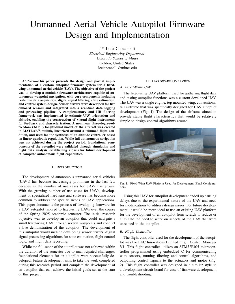
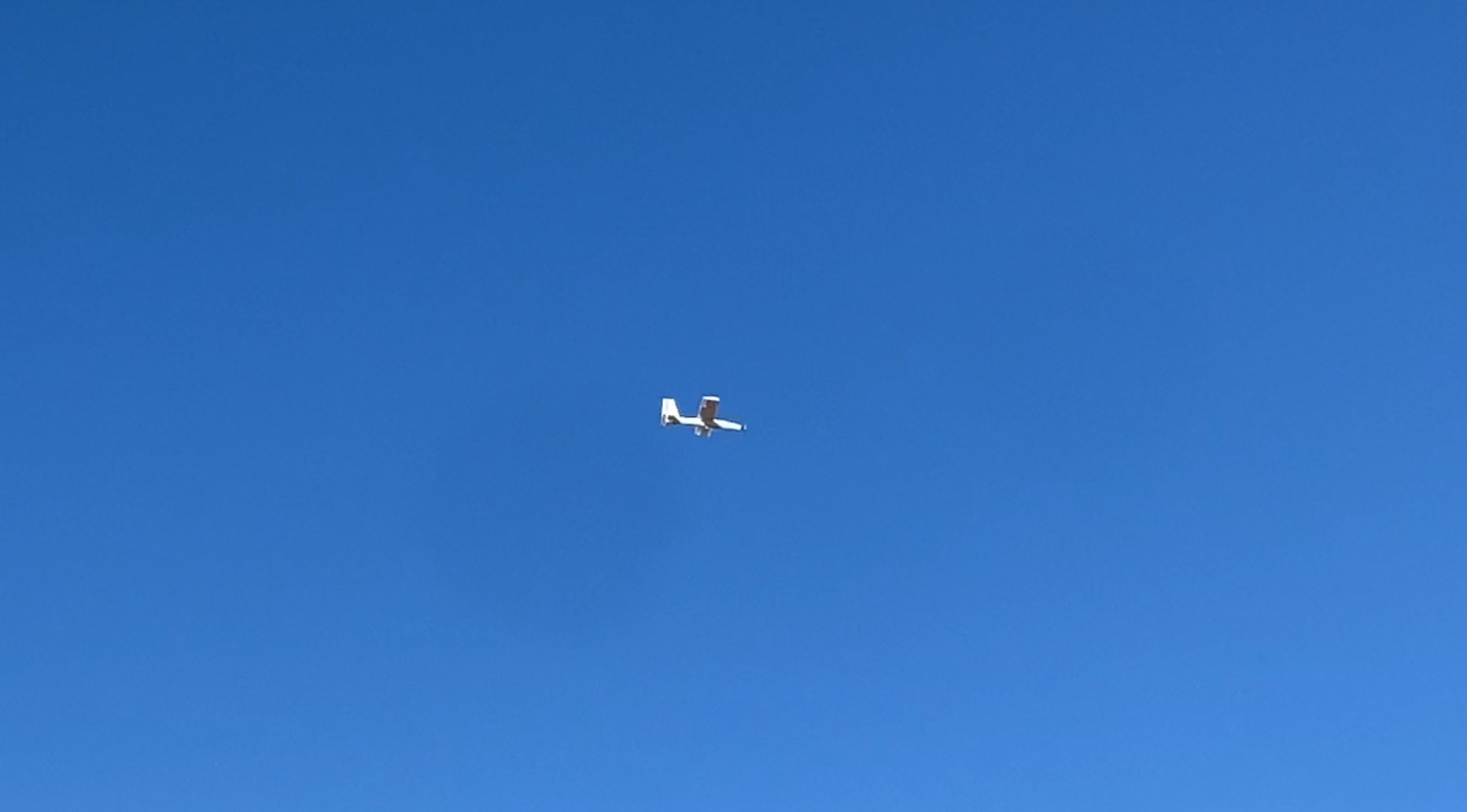
This flight controller was developed to help me gain a better understanding of the fundamentals of flight control hardware and firmware. The flight controller was specifically targeted towards fixed-wing UAV platforms with the goal of full autonomous flight capability. I designed the flight controller hardware during my first year of college and developed the firmware for the flight controller as part of an independent study for my senior year.
STM32F4 High Performance MCU
6-Axis IMU, Magnetometer, Barometer, and Thermometer
UART, I2C, ADC, SBUS, and PWM Output
The first step of development was to find a reference design that would introduce me to the basics of PCB flight controller design. Given that I started this design before I had taken any electrical engineering classes, I was primarily working based off of experience with an Arduino based flight data recorder project and off-the-shelf flight controllers. I utilized basic design elements from the reference design (HADES Flight Control System) and modified them to fit into the scope of the planned capabilities of my flight controller.
After producing an initial architecture for the flight controller, ICs were chosen based on desired specs and availability (this design was created in 2022 when many ICs were back ordered due to shortages). The JLCPCB assembly parts library was used to source parts to allow JLC to both manufacture the PCB and assemble it.
Once all the non-passive ICs had been chosen, an electronic schematic was created in EasyEDA (EasyEDA was chosen because this project was being done as a project under my company and EasyEDA was free). The configuration of passive components was based on design methodology used in the reference design (HADES Flight Control System) as well as other open-source PCB projects.
The schematic was used to generate all the components and connections in the EasyEDA PCB designer tool. Trace widths and routes were manually created in the designer using educational PCB design resources for guidance. A two-layer board layout was chosen as the board size could be larger for testing and to minimize manufacturing cost.
Gerber files were generated from the EasyEDA PCB designer tool and sent to JLCPCB for manufacturing. JLCPCB checked the Gerber files for any large design errors, created the PCB, ran a flying probe test electrical test, and used ICs from their warehouse to assemble to board. The board was then packaged and shipped.
After receiving the board, STM32CubeIDE was used to set up a basic test script to check for proper functionality of the microcontroller and on-board sensor ICs. Power was also supplied to all on-board regulators to check for voltage stability under expected loads. After the hardware was checked for proper functionality, the flight controller was set aside until the beginning of the firmware development which started my senior year.
After taking classes going over embedded systems, digital signal processing, modern control systems, etc. I gained the necessary background knowledge to develop the firmware for the flight controller as part of an independent study. The initial firmware that developed was purely for collecting raw sensor measurements and recording them to a micro-SD card. These measurements recordings would be imported to MATLAB for easier development of filtering algorithms and control loops.
The flight controller with the flight data recording firmware uploaded was mounted inside the 3D Printed Test Plane for data collection. Flight tests were conducted at a model airfield with the flight controller constantly collecting sensor data and storing it to an on-board micro-SD card. These flight tests resulted in ten sets of flight data that could be analyzed in MATLAB.
The ten sets of flight data were formatted and imported to MATLAB for analysis and development of filtering algorithms. Research was conducted to determine typical filters used to remove noise from raw sensor measurements and to transform raw sensor measurements into useful measurements for automated control. These filters were implemented in MATLAB and tested on the imported flight data.
After developing the primary measurement filtering algorithms, research was conducted into state-space control models used in fixed-wing aircraft control systems. Simulink was utilized to create control loops for a 3 degree of freedom altitude controller using the output of the primary measurement filtering algorithms as the input to the control loop.
The development of the Flight Control Manager V1 helped create a flight controller architecture that could be refined through future iterations. Despite the full autonomous flight functionality not being realized in the span of the project, a solid foundation for a flight controller that could be capable of autonomous flight in the future. This project helped develop a useful workflow for developing hardware and firmware for an embedded systems solution to an electrical engineering problem.
I learned a tremendous amount about the fundamentals of hardware, firmware, filtering, and control loop through the development through this project. This project served as a great foundation for developing applicable aerospace engineering skills. Currently I am developing a second version of the flight control manager that addresses issues found in the previous design and extends the capability of the on-board hardware. The goal for the second version of the flight control manager is to demonstrate real world autonomous flight capability.