X-1 Autonomous Glider UAV

AIAA Design Build Fly Competition Autonomous Glider

Project Overview

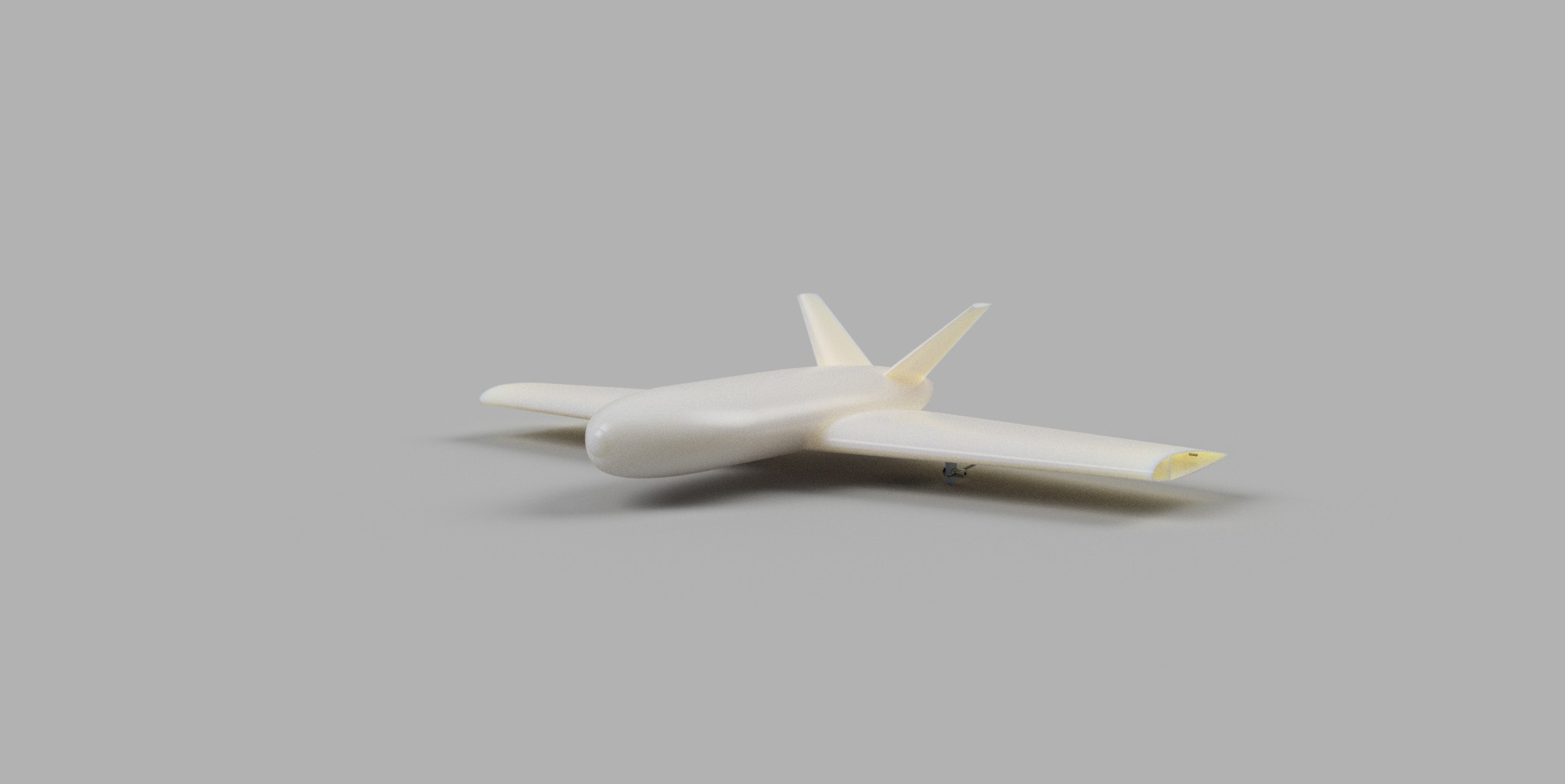
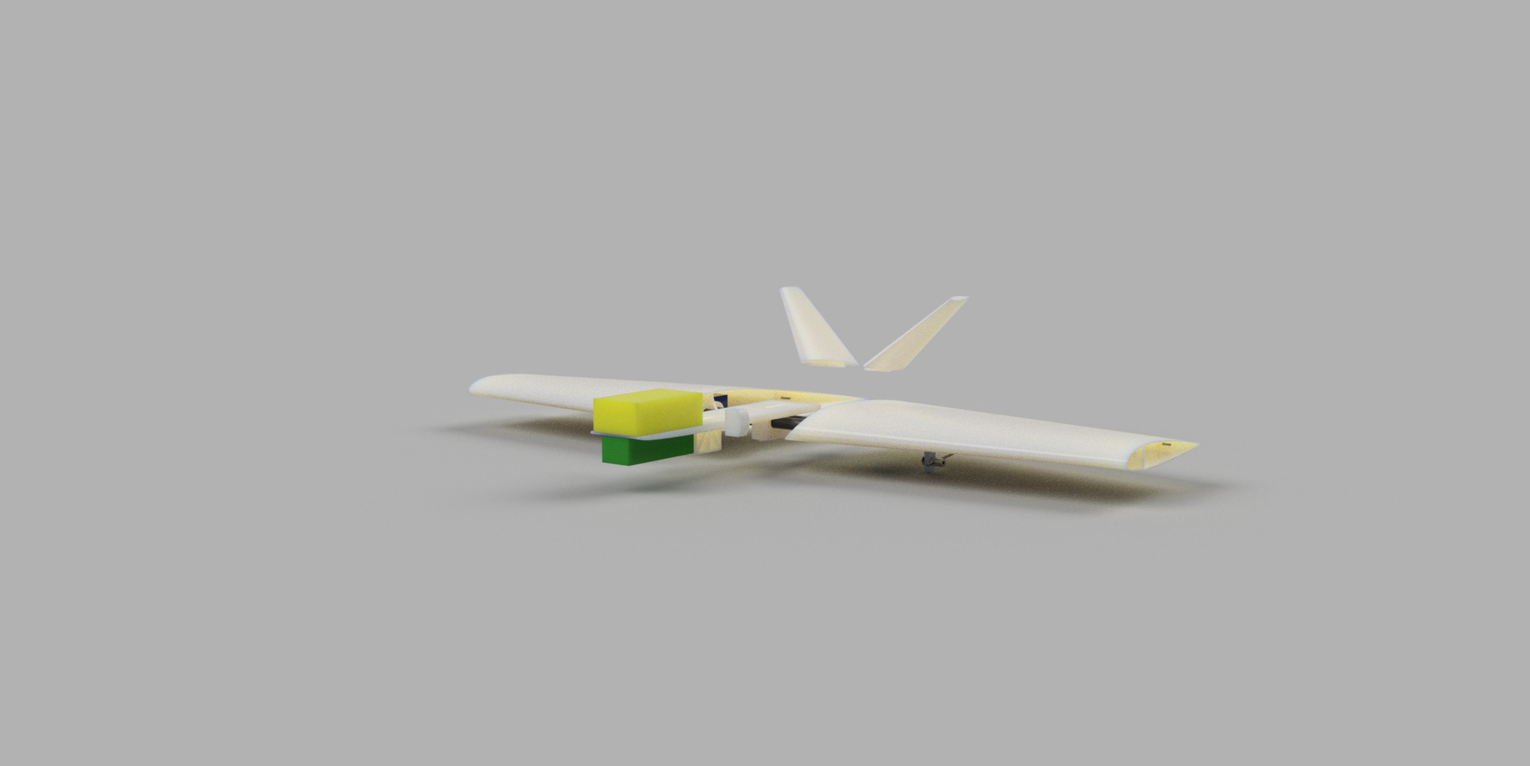
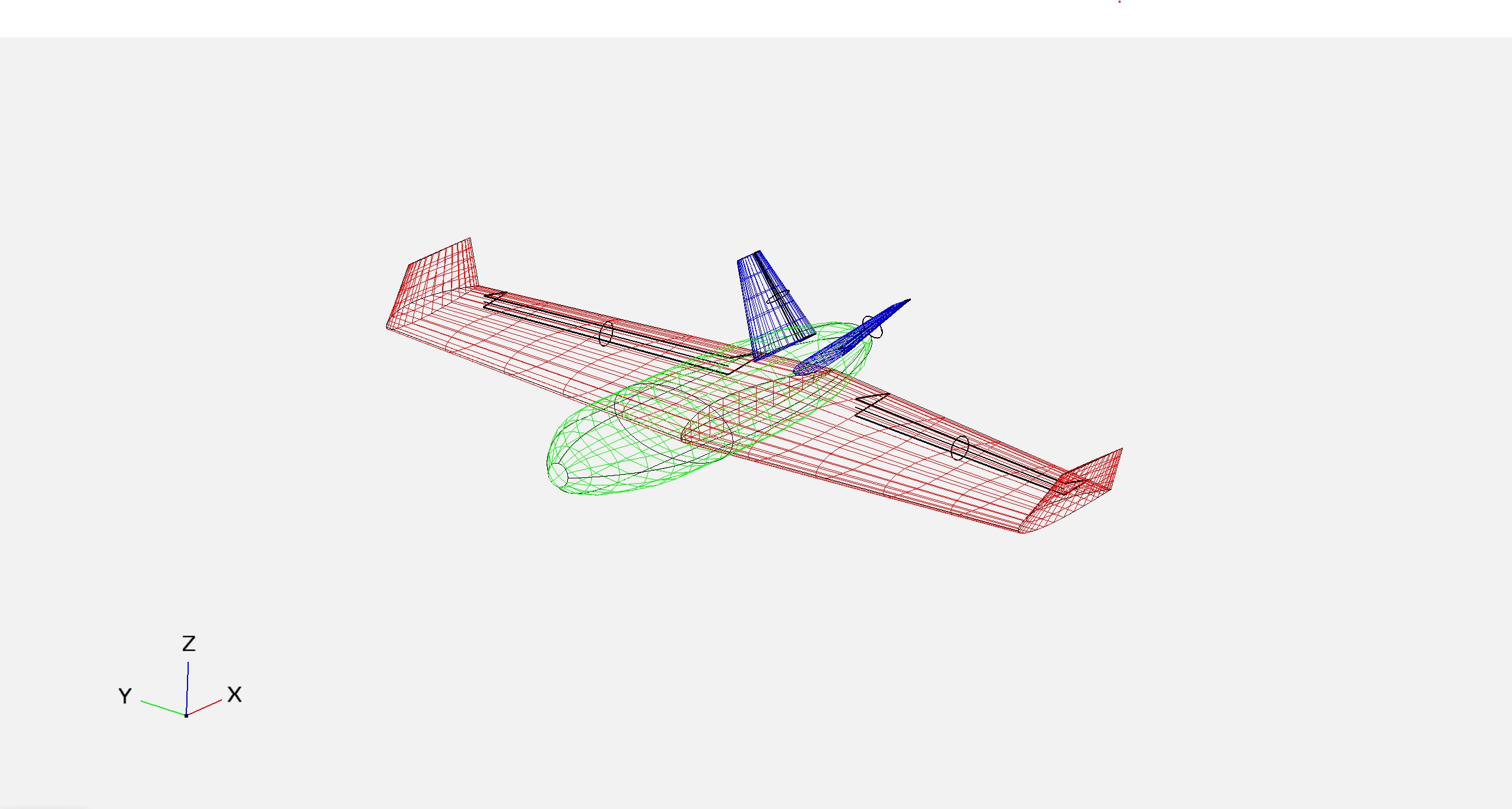
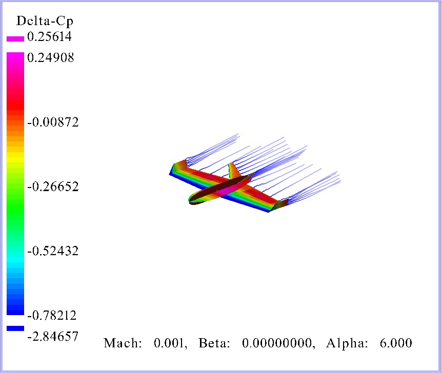
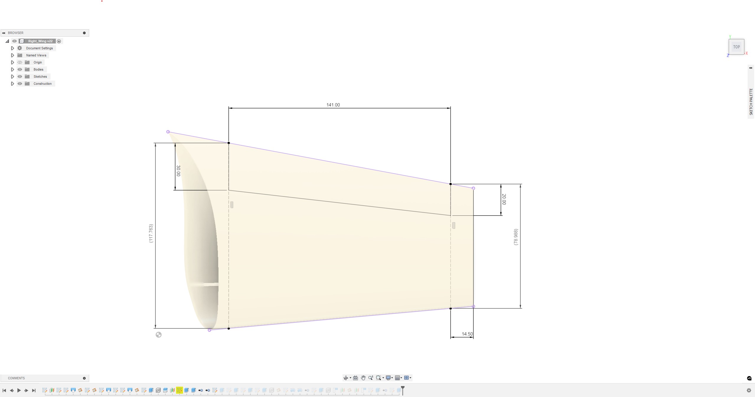
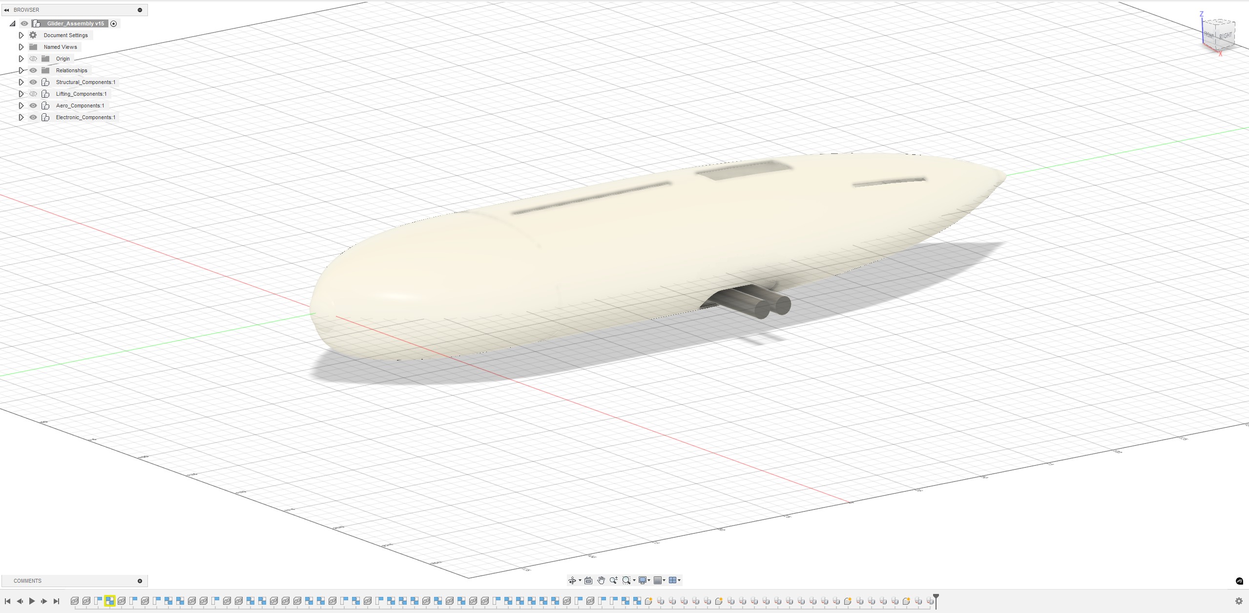
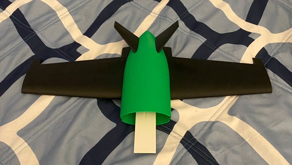
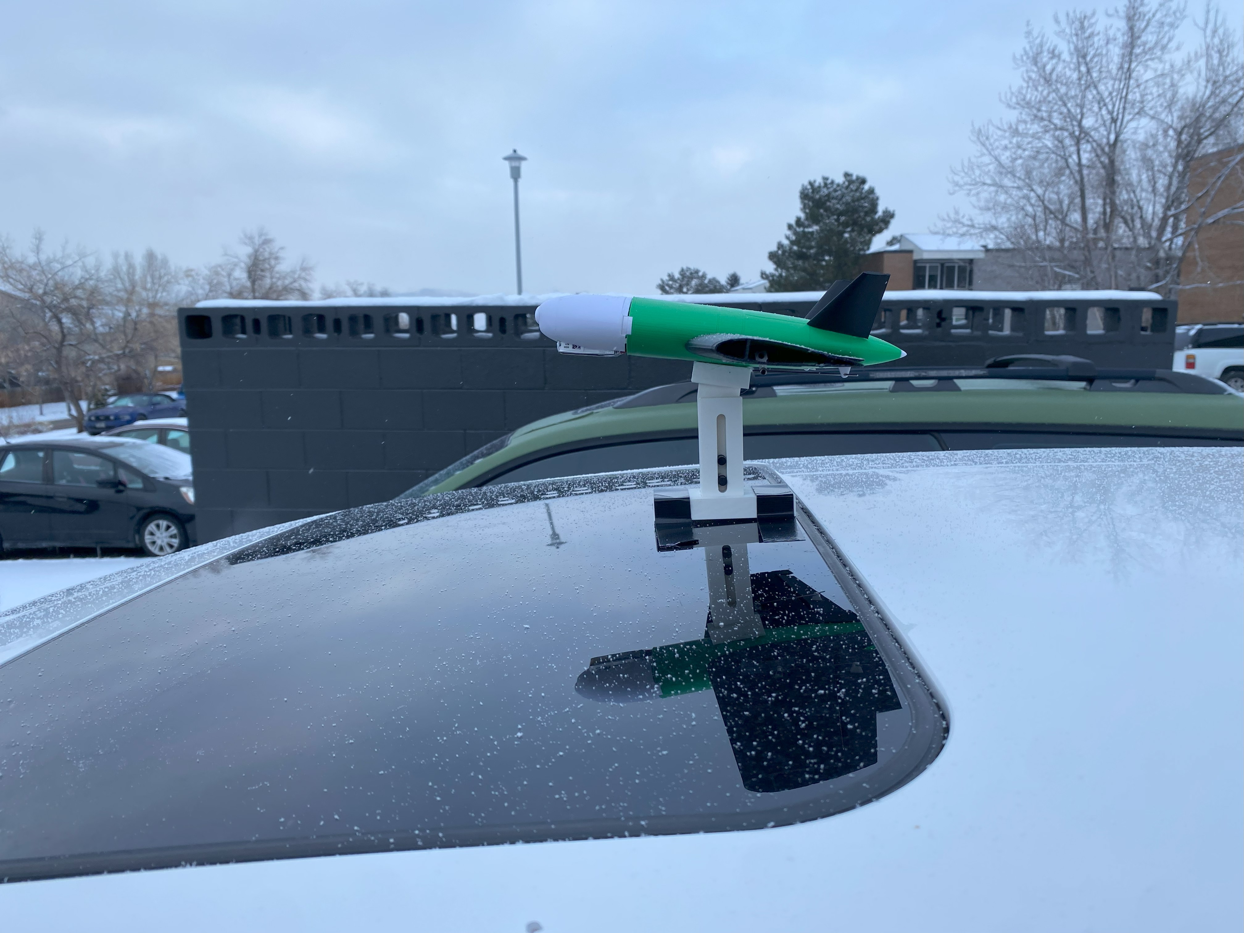
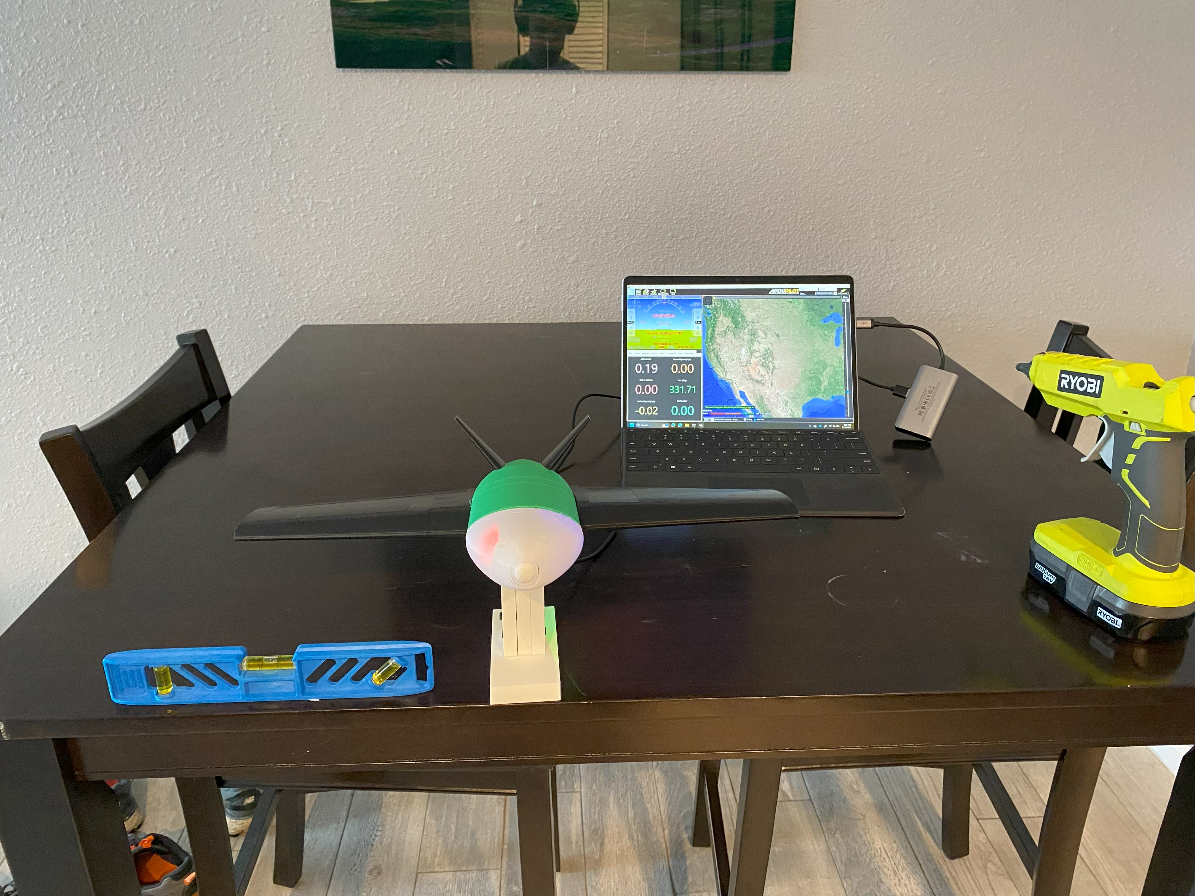
This UAV was developed for the AIAA Design Build Fly 24/25 Competition to be remotely deployed from a mothership aircraft and autonomously land in a designated zone. The primary requirements for the autonomous glider were that it had to be under 250 grams and had to be fully autonomous (no ground control). The design, manufacturing, and testing process for developing the 3D Printed Test UAV was utilized for the development of the autonomous glider. This process resulted in a first successful test flight being approximately one month from the creation of the initial conceptual design for the airframe.

1 / 2
2 / 2

Key Specifications

Wingspan

400 mm

Airframe Mass

221 g

Cruise Speed

13 m/s (29 mph)

Design and Developement Process

Airframe Geometry

The preliminary airframe geometry was designed in OpenVSP and was inspired by the Flite Test Goblin (a small powered flying wing UAV). The geometry was adjusted based on VSPAERO simulation results to make the airframe stable, maximize L/D ratio, and achieve other desirable flight characteristics.


Airframe Characterization

The OpenVSP geometry was simulated using VSPAERO under expected flight conditions for deployment at the local airfield and competition airfield. Alpha and Beta (aka pitch and yaw) were varied through testing to find a stable configuration and generate aerodynamic coefficient graphs over the range of flight conditions.


Part Selection

Using data acquired from the airframe characterization and typical design specification for similar sized UAVs off-the-shelf parts for the airframe, surface actuators, and autopilot avionics were sourced. Off-the-shelf parts were used wherever possible to minimize the number of custom parts designed.


Part Modeling

Both custom and off-the-shelf parts were modeled in Autodesk Fusion 360 to allow for the creation of a full airframe assembly in Fusion 360. Custom parts were modeled to allow for PLA additive manufacturing, and their associated masses were estimated using Fusion 360.


Assembly Modeling

Using the parts modeled in Fusion 360, sub-assemblies and the full airframe assembly were modeled. The full airframe assembly allowed for the estimation of the total mass and location of the center of mass. Necessary adjustments were made to fix any part conflicts and adjust location of the center of mass to match the OpenVSP geometry.


Custom Part Manufacturing

Custom parts were exported to STL, sliced in Bambu Studio, and manufactured using a Bambu P1S 3D printer. Parts were printed using standard PLA.


Airframe Assembly

Once all parts had been sourced and manufactured the airframe was assembled and electronics were integrated. Necessary part modification was made to ensure proper assembly. The airframe was then weighed to determine final mass, and the CG location was estimated using balancing.


Cruise Configuration Verification

After the final assembly of the airframe was complete a test rig was designed and manufactured to attach the airframe to the top of a car. The rig allowed for the airframe to move up and down freely to visually confirm that the airframe would generate enough lift to sustain flight at the estimated cruise speed.


Configure Ardupilot for Autonomous Flight

Once the cruise speed was verified within a reasonable margin of error (under 10 percent from estimated), the flight controller was configured for autonomous flight using Ardupilot. The stable cruise configuration that was determined in OpenVSP was configured in Ardupilot and the initial flight path was set as a descending circular pattern. The circular pattern would be used to determine controllability of the airframe and would be later changed to the pattern specified by AIAA DBF.

Flight Testing

Finally, the autonomous glider was taken to a model airfield and deployed from the AIAA DBF mothership. The first deployment successfully proved airframe stability and controllability. Unfortunately, there was only one other successful deployment of the autonomous glider due to issues with the deployment mechanism jamming and issues with the mothership. However, the two successful deployments showed promising results that indicated that the autonomous glider would have been able to successfully complete the competition mission.

Results

  • Pitch and Yaw Stability Confirmed
  • Autonomous Flight Control Capabilities Confirmed
  • Glider Reusability Confirmed

Real world flight testing proved that the airframe demonstrated flight characteristics that matched simulation predictions within a reasonable margin and that the autopilot was capable of controlling the airframe. The primary issue that arose was inconsistency in the deployment mechanism and difficulties with the performance of the mothership. Given a more reliable method of deployment for the autonomous glider, I believe that the AIAA DBF mission could have been demonstrated to be within the capabilities of the glider.

Impact & Next Steps

This project helped me evaluate my design methodology on a UAV problem that had specific requirements that were set by a design competition. I also learned how to use Ardupilot and integrate it into my projects. Moving forward, this airframe could be reused for a mission with similar autonomous navigation requirements with minimal design changes. Furthermore, the avionic configuration could be adapted to other airframes that would benefit from autonomous navigation capabilities. I plan on using the knowledge gained from this project to continue designing airframes and push the bounds of UAV technologies and applications.