3D Printed Test UAV

Pushing the Bounds of Additive Manufacturing for UAVs

Project Overview

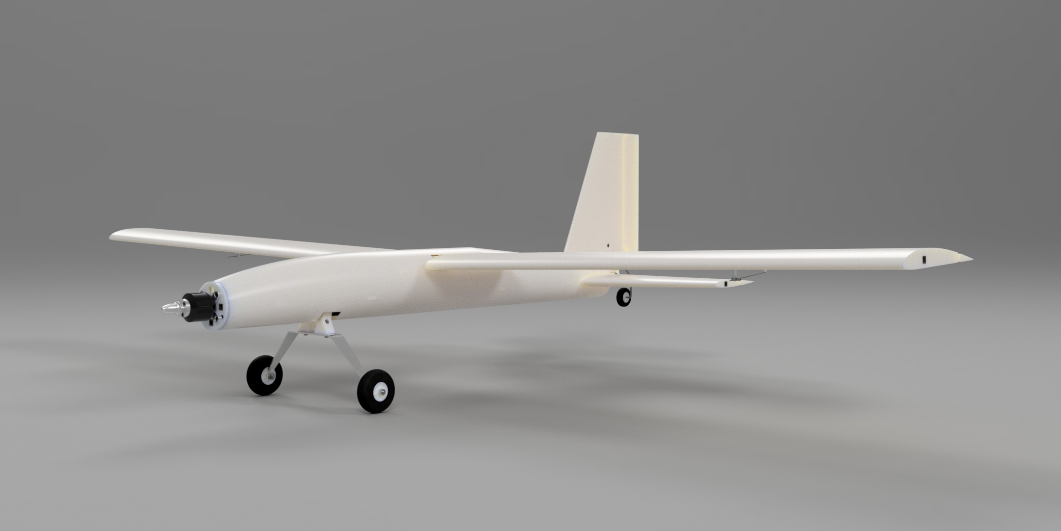
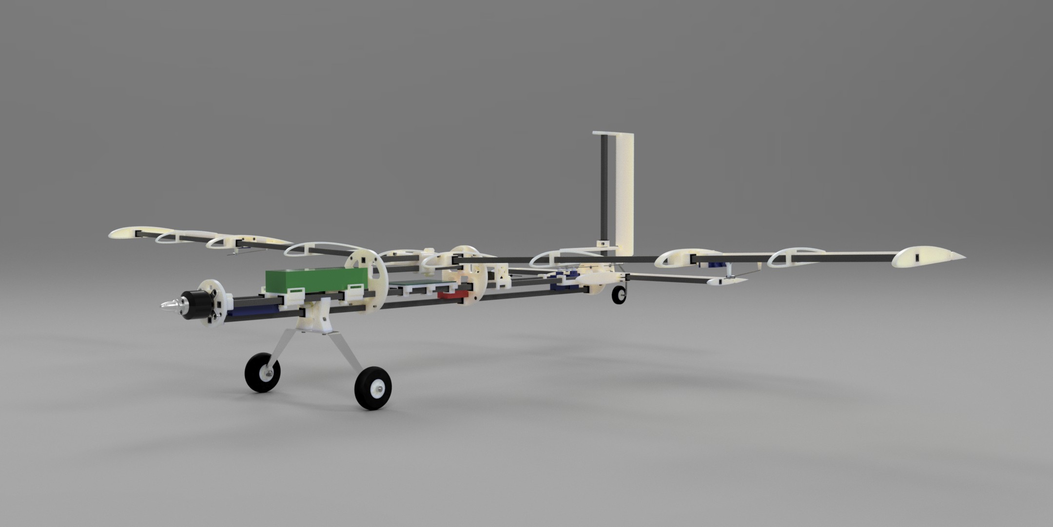
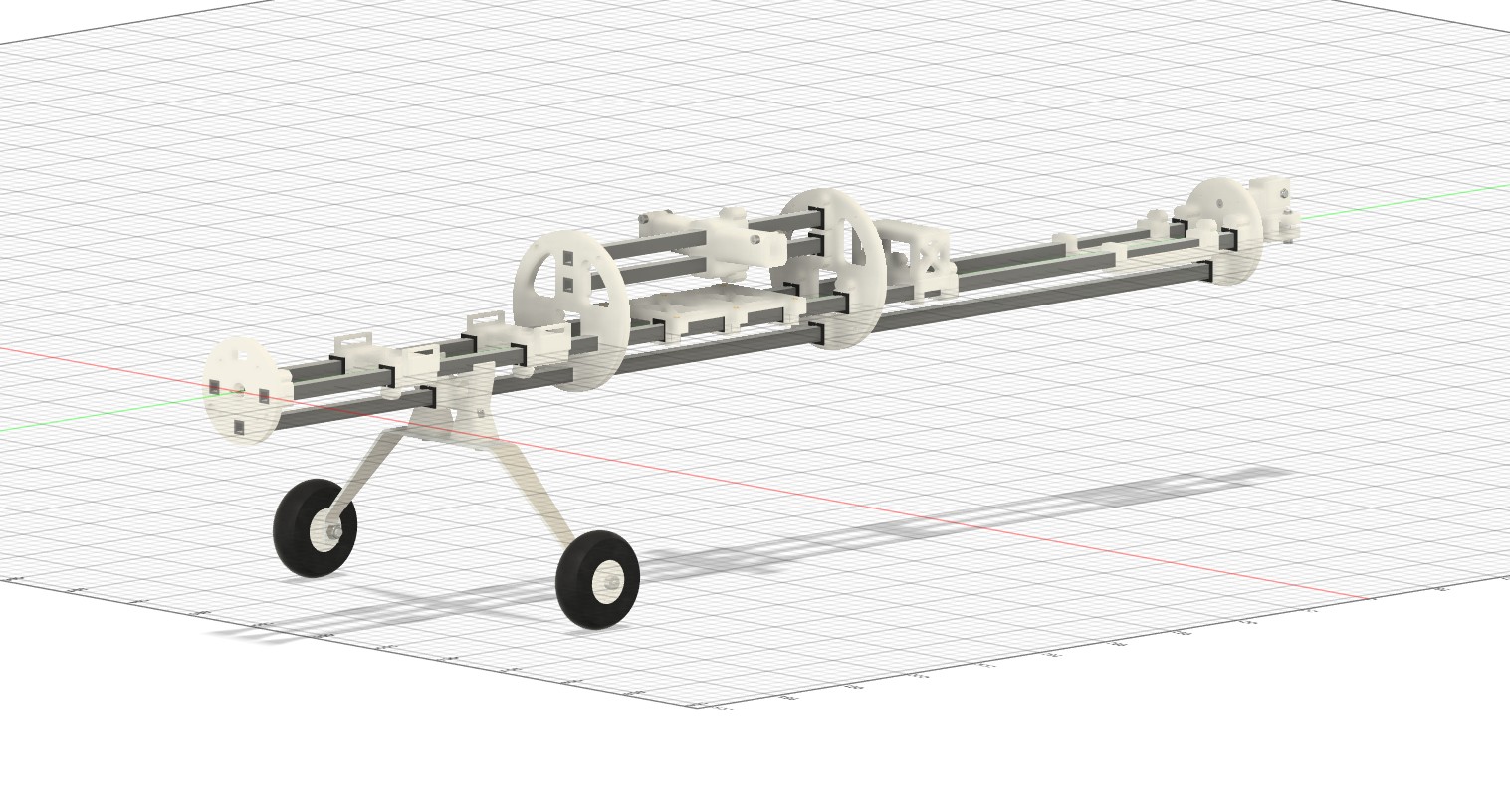
This UAV was developed to evaluate additive manufacturing techniques for UAVs, develop modular components that can be serviced/replaced, and refine my UAV design process. The primary motivation for this project was to construct test, assess, and adjust design/manufacturing/testing processes to create an ideal workflow for creating robust UAVs to meet design requirements.

1 / 2
2 / 2

Key Specifications

Wingspan

1500 mm

Airframe Mass

2.2 kg

Cruise Speed

17 m/s (38 mph)

Design and Development Process

Airframe Geometry

The preliminary airframe geometry was designed in OpenVSP based on initial specifications (wingspan, wing placement, tail configuration, etc.). The geometry was adjusted based on VSPAERO simulation results to make the airframe stable, maximize L/D ratio, and achieve other desirable flight characteristics.


Airframe Characterization

The OpenVSP geometry was simulated using VSPAERO under expected flight conditions for the airfield that would be used for testing. Alpha and Beta (aka pitch and yaw) were varied through testing to find a stable configuration and generate aerodynamic coefficient graphs over the range of flight conditions.


Part Selection

Using data acquired from the airframe characterization and typical design specification for similar sized UAVs off-the-shelf parts for the airframe, power plant, surface actuators were sourced. Off-the-shelf parts were used wherever possible to minimize the number of custom parts designed.


Part Modeling

Both custom and off-the-shelf parts were modeled in Autodesk Fusion 360 to allow for the creation of a full airframe assembly in Fusion 360. Custom parts were modeled to allow for PLA/TPU additive manufacturing, and their associated masses were estimated using Fusion 360.


Assembly Modeling

Using the parts modeled in Fusion 360, sub-assemblies and the full airframe assembly were modeled. The full airframe assembly allowed for the estimation of the total mass and location of the center of mass. Necessary adjustments were made to fix any part conflicts and adjust location of the center of mass to match the OpenVSP geometry.


Custom Part Manufacturing

Custom parts were exported to STL, sliced in Bambu Studio, and manufactured using a Bambu P1S 3D printer. Parts that needed rigid characteristics were printed using PLA and parts that needed flexible characteristics were printed using TPU.


Airframe Assembly

Once all parts had been sourced and manufactured the airframe was assembled and electronics were integrated. Necessary part modification was made to ensure proper assembly. The airframe was then weighed to determine final mass, and the CG location was estimated using balancing.


Surface Actuation and Motor Testing

After the final assembly of the airframe was complete the electronic subsystems were evaluated to ensure proper operation. Calibrations to control surface actuators were made to adjust control surface throws to be within desired specifications. The motor was run at full throttle with the propeller installed to test for excessive airframe vibrations.


Flight Testing

Finally, the UAV was taken to a model airfield for a maiden test flight and further testing of aircraft flight dynamics. The LEC Innovations Flight Command Manager V1 was installed to gather raw flight data to determine actual flight characteristics. Small design changes were made and implemented based on issues found during flight testing.

Results

  • Pitch and Yaw Stability Confirmed
  • Approximate Flight Time of 10 Minutes (based on battery consumption for shorter flights)
  • Measured Cruise Speed of 20 m/s (based on average GPS ground speed measurements)

Real world flight testing proved that the airframe demonstrated flight characteristics that matched simulation predictions within a reasonable margin. This proved that the validity of the geometry and simulation portions of the design process. Though the aircraft flew and was stable, the high airspeed combined with the high inertia of airframe (compared to similar sized UAVs) made the UAV relatively difficult to pilot. While improvements could certainly be made to the airframe, the overall project successfully achieved the primary goal of integrating additive manufacturing into UAV production and validated a baseline design process.

Impact & Next Steps

This project helped me develop an understanding of the full design process for UAVs from napkin sketches to a flying aircraft. It also helped me develop forward thinking manufacturing techniques that provide advantages over more traditional manufacturing processes. There are not any current plans to revise the airframe as the primary goal of this project was to gain knowledge of UAV and general aerospace engineering. Aspects of the design process in this project are planned to be used in future UAV projects.